Click Below To Share & Ask AI to Summarize This Article
Save time and get the key takeaways instantly. Choose your favourite AI assistant to read and analyse this page for you.
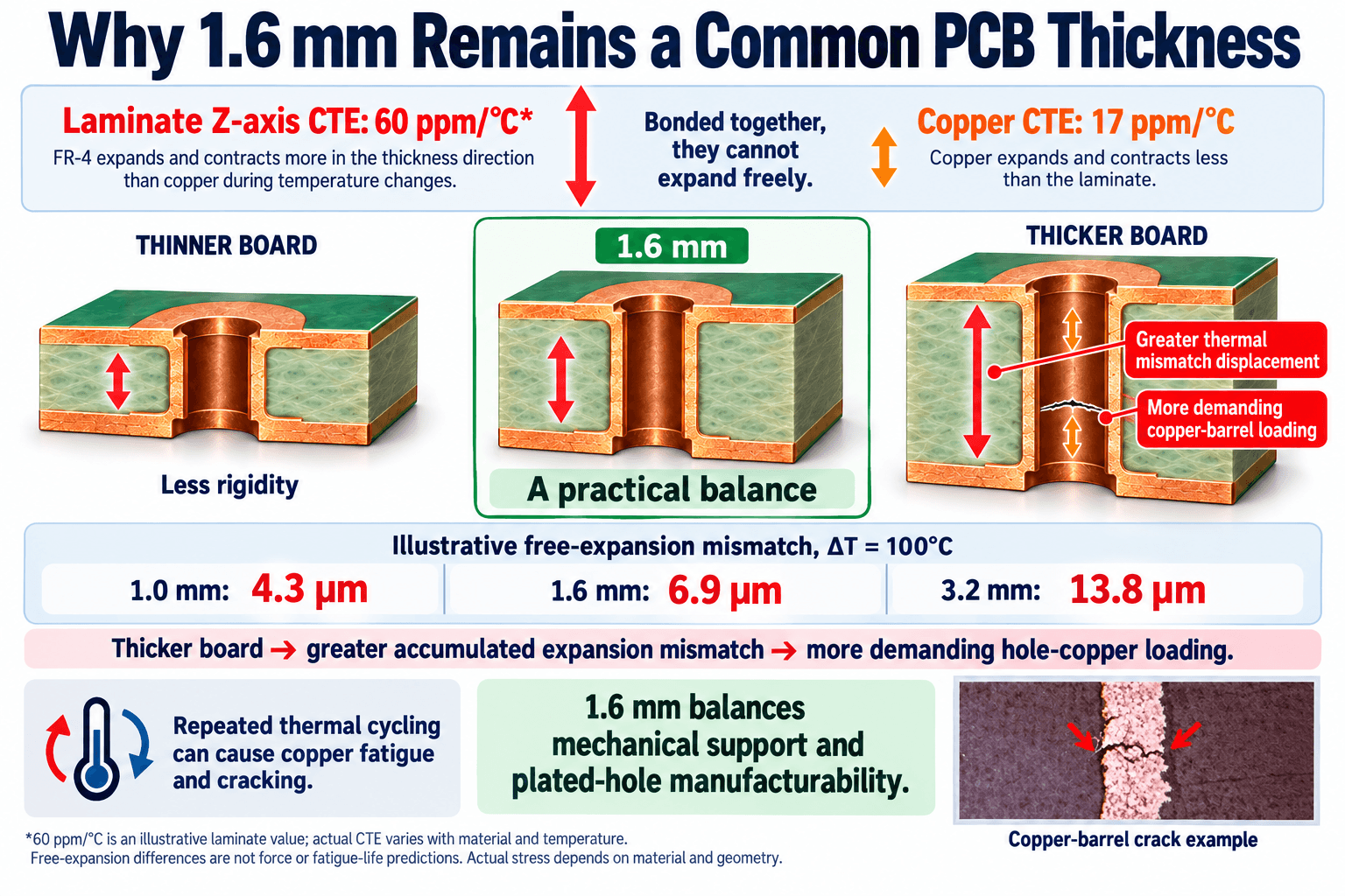
A PCB can pass electrical testing before shipment and still fail after extended use. In a technical article, Tony Niu, a PCB manufacturer with 25 years of industry experience, says one possible cause is the difference in thermal expansion between the copper lining of plated through-holes and the surrounding laminate. He uses that mechanism to explain why a thicker board does not automatically mean a more reliable one, and why 1.6 mm remains a common choice for conventional rigid FR-4 products.
Copper and Laminate Expand by Different Amounts
According to Niu, copper has a linear coefficient of thermal expansion (CTE) of about 17 ppm/°C. FR-4, a resin reinforced with glass fibers, is held back in the plane of the board by the glass, but typically expands more through its thickness, the Z-axis, and that expansion generally rises substantially above the glass transition temperature. When a board heats, the laminate wants to expand more through its thickness than the copper barrel does. Because the two are bonded, the laminate forces the copper to deform and builds stress in the barrel and its connections.
A single temperature change may not cause serious damage, Niu notes, but products heat up in operation and cool down after shutdown, and ambient temperature adds further cycles. Repeated deformation can create small fatigue cracks that grow until the copper fractures. Before a connection fails completely, the product may develop intermittent faults. Shipment testing, he says, confirms continuity at that moment but does not by itself show resistance to long-term thermal cycling.
Why Thickness Raises the Stakes
Niu gives a simplified relationship for free Z-axis expansion: original thickness multiplied by Z-axis CTE and by temperature change. To illustrate, he assumes a laminate Z-axis CTE of 60 ppm/°C, a copper CTE of 17 ppm/°C and a 100°C temperature change:
| Board thickness | Difference in free expansion |
|---|
| 1.0 mm | 4.3 μm |
| 1.6 mm | 6.9 μm |
| 2.4 mm | 10.3 μm |
| 3.2 mm | 13.8 μm |
He stresses that these are illustrative values, not actual copper-barrel strain, tensile force or fatigue-life predictions, since real behavior also depends on material stiffness, hole geometry and the mechanical properties of the copper. His point is that thicker boards give the plated-hole structure more expansion displacement to accommodate.
Thickness also makes plating harder. For a 0.30 mm drilled hole, Niu says, a 1.6 mm board has an aspect ratio of about 5.3:1, while a 3.2 mm board is about 10.7:1. Deeper holes generally make hole-wall preparation, solution exchange and uniform copper deposition more difficult, and locally thin copper or plating defects can become weak points under thermal cycling. He advises evaluating board thickness and hole diameter together and discussing hole structure and process capability with a PCB manufacturer before production.
Why 1.6 mm Is a Practical Compromise
Making a board thinner is not a simple fix, Niu says, because a thinner board bends more readily under comparable support conditions, which can strain solder joints, components and connection points. Thickness therefore has to balance mechanical rigidity against a plated-hole structure that can be manufactured consistently and withstand thermal stress.
Based on his experience, he says 1.6 mm often provides a useful balance for conventional rigid FR-4 products, offering appropriate mechanical support while through-hole manufacturing remains well established for common hole sizes. He adds that it is not the only suitable thickness: large boards, heavy connectors or particular stack-ups may need thicker construction, compact products may need thinner boards, and multilayer designs must also account for layer count, dielectric thicknesses, copper weights and interconnection structure.
Beyond Thickness
Niu lists the other factors that determine long-term plated-hole reliability:
- Laminate Z-axis expansion over the relevant temperature range
- Hole copper thickness, uniformity and ductility
- The aspect ratio created by board thickness and hole diameter
- Hole-wall preparation and plating quality
- Thermal cycles during assembly and actual operation
For high-reliability PCB projects, he says these factors should be reviewed together and verified through inspections and testing appropriate to the application. In his summary, material properties determine how much the structure wants to expand, geometry determines how that expansion is constrained, and copper quality helps determine how well the connection survives repeated deformation.
Stay Ahead of the News
Get the latest business news and company spotlights delivered to your inbox. No spam, unsubscribe any time.
We respect your privacy. Unsubscribe at any time.